 EN
 AR
 HR
 CS
 NL
 FR
 DE
 IT
 JA
 KO
 NO
 PL
 PT
 RO
 RU
 ES
 SV
 TL
 ID
 VI
 MT
 TH
 TR
 AF
 MS
 AZ

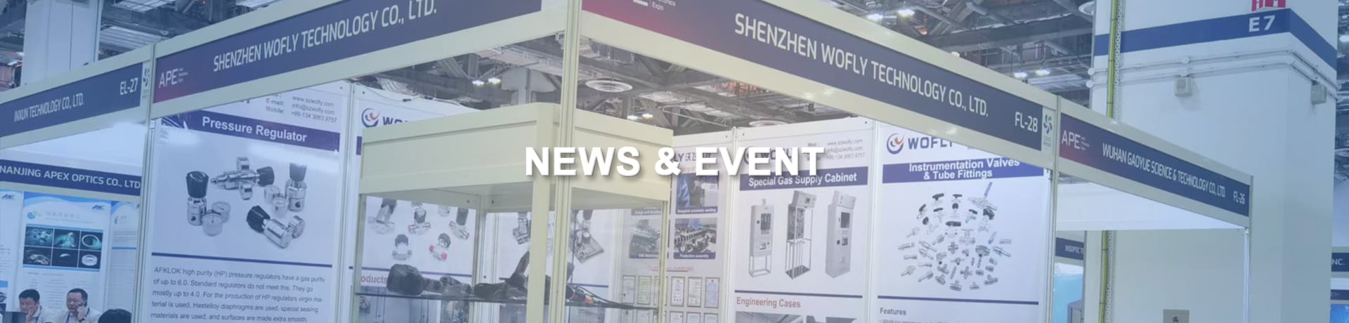
WR11 Series High-Purity Diaphragm Pressure Regulator: Engineering Selection & Technical Guide
In modern analytical laboratories, semiconductor specialty gas piping, high-purity chemical processing, and pilot fluid systems, consistent delivery pressure and ultra-clean fluid containment directly govern instrumentation baseline stability, yield rates, and operational safety. The WR11 Series Single-Stage Diaphragm Pressure Regulator is engineered specifically for medium-to-high pressure specialty gases, toxic media, and corrosive fluid delivery. Featuring a metallic convoluted diaphragm sensing architecture and precision bubble-tight sealing mechanics, the WR11 delivers micro-fine setpoint sensitivity and extended cycle life even under supply inlet pressures up to 3,500 PSIG (241 bar).
To assist instrumentation engineers, gas delivery skid integrators, and fluid system procurement specialists in selecting the optimal configuration, this comprehensive engineering guide analyzes the WR11 Series technical specifications, dimensional drawings, nitrogen flow and droop curves, and full model ordering matrix.
1. Core Technical Specifications and Structural Features of WR11 Regulators
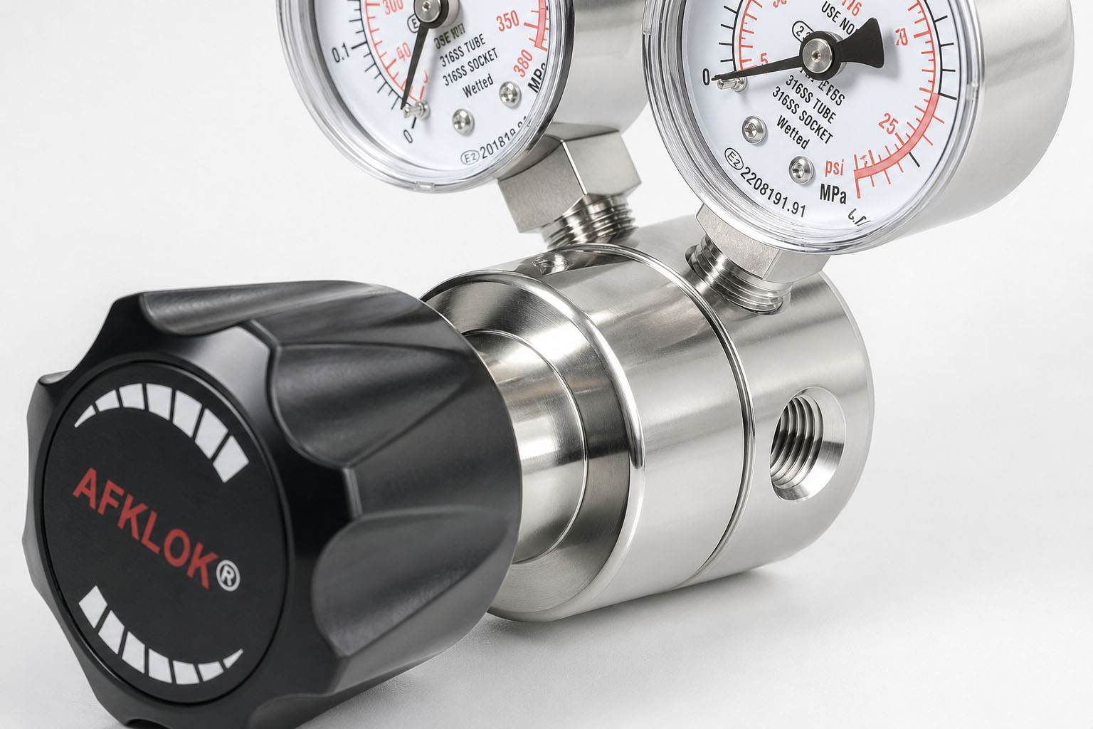
The WR11 Series utilizes a direct-acting, single-stage tied-diaphragm mechanical force-balance design. Every internal component is optimized for low internal volume, rapid dynamic response, and repeatable setpoint stability.
1.1 Key Pressure and Flow Parameters (Inlet 600/3500 PSIG, Cv 0.20/0.09)
The WR11 Series accommodates diverse upstream supply pressures and downstream delivery targets:
- Maximum Inlet Pressure ($P_1$): Offered in two standard ratings: 600 PSIG (41.4 bar) for pipeline secondary regulation and 3,500 PSIG (241 bar) for primary high-pressure gas cylinder manifolds.
- Outlet Pressure Ranges ($P_2$): Divided into six calibrated spring ranges to ensure high control resolution across all setpoint bands: 0–30 PSIG, 0–60 PSIG, 0–100 PSIG, 0–150 PSIG, 0–250 PSIG, and 0–500 PSIG.
-
Flow Coefficient ($C_v$):
- $C_v = 0.20$ for the 600 PSIG inlet version, optimized for high volumetric throughput in distribution lines;
- $C_v = 0.09$ for the 3,500 PSIG inlet version, featuring a micro-orifice trim that prevents high-velocity erosion and delivers precise setpoint adjustment.
- Operating Temperature Range: -40°C to +74°C (-40°F to +165°F), ensuring flawless mechanical elastomeric and spring response across extreme ambient temperatures.
- Standard Port Threading: Inlet, outlet, and auxiliary gauge ports are uniformly machined with precision 1/4" NPT female threads.
1.2 Materials Engineering: PCTFE Seat and 316L / Hastelloy C-276 Convoluted Diaphragm
Material selection in the WR11 balances chemical inertness, mechanical compliance, and outgassing prevention:
- Valve Seat Material: Standardized with high-density polychlorotrifluoroethylene (PCTFE / Kel-F). PCTFE delivers exceptional resistance to cold flow, zero moisture absorption, and near-zero outgassing. It forms an ANSI Class VI bubble-tight soft seal against the stainless poppet, preventing internal gas bypass.
- Sensing Diaphragm: Fabricated from Hastelloy C-276 or 316L Stainless Steel. The convoluted profile generates an expanded linear elastic travel zone with minimal mechanical hysteresis, surviving millions of pressure balancing cycles without work hardening or calibration drift.
- Integrated Sintered Inlet Filter: A 20-micron 316L stainless steel sintered filter element is factory-installed within the 1/4" NPT inlet port. This filter captures weld slag, pipe scale, and cylinder debris, protecting the PCTFE seat from particle impingement and premature leakage.
1.3 Helium Leak Integrity and ASTM G93 Level C Cleanliness Standards
In reactive, pyrophoric, or toxic gas service (such as silane, ammonia, hydrogen chloride, or carbon monoxide), leak tightness is paramount:
- Helium Leakage Specifications: Certified internal across-the-seat leak rate of $\le 1 \times 10^{-7}\ \text{mbar}\cdot\text{l/s}$, and an external helium inboard/outboard leak rate of $\le 1 \times 10^{-9}\ \text{mbar}\cdot\text{l/s}$, matching semiconductor and analytical instrumentation standards.
- Cleaning and Packaging Protocol: Fully compliant with ASTM G93 Level C, incorporating ultrasonic multi-stage degreasing, DI water rinsing, heated particle-free nitrogen dry-down, and cleanroom vacuum dual-bag packaging. This standard qualifies the WR11 for clean Oxygen Service, eliminating combustible hydrocarbon film ignition risks.
2. Dimensional Drawings and Porting Configurations (Panel & Bottom Mounting)
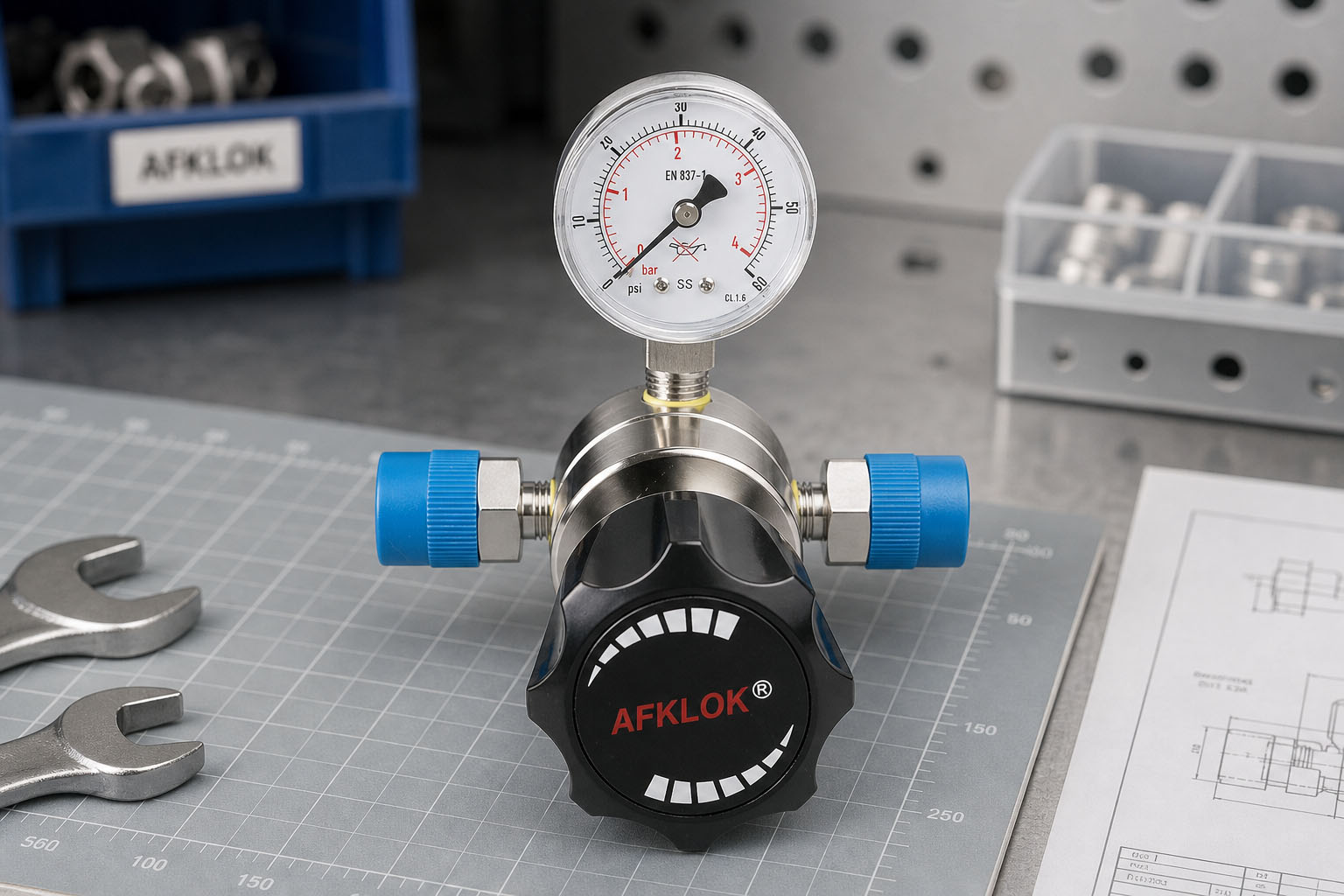
The compact envelope of the WR11 facilitates seamless integration into analytical instrumentation enclosures, gas cabinet panels, and gas distribution manifolds.
2.1 Overall External Dimensions and Envelope Requirements (Ø58.5mm Knob, Ø50.3mm Body)
Engineering dimensional data (referenced in inches and millimeters):
- Adjustment Knob: Ergonomic black knurled hand knob with an outer diameter of $\varnothing 2.3$ in (58.5 mm), providing smooth torque adjustment with low operator fatigue.
- Vertical Envelope: Total installed height ranges from 4.72 to 5.12 in (120 to 130 mm) from the bottom body plane to the top of the knob at full open adjustment.
- Valve Body Geometry: Hexagonal forged body with an outer diameter of $\varnothing 1.98$ in (50.3 mm). The distance from the bottom mounting plane to the centerline of the 1/4" NPT fluid ports is fixed at 0.75 in (19.1 mm), ensuring standardized center-height alignment across piping headers.
2.2 Porting Topologies: Type A, Type B, and Type D Configurations
The WR11 body features four radial ports at 90-degree orientations, available in three standardized flow layouts:
- Type A (1-In / 1-Out): Straight-through inline configuration (Port 1 inlet, Port 2 outlet). Ideal for inline piping skids where remote pressure transmitters are installed downstream and local mechanical gauges are unnecessary.
- Type B (1-In / 2-Out): Three-port configuration (Port 1 inlet, Port 2 outlet/gauge, Port 3 outlet). Enables the installation of a single delivery pressure gauge alongside an active outlet stream.
- Type D (2-In / 2-Out): Four-port universal configuration. Port 1 is the high-pressure gas inlet; Port 2 accommodates a high-pressure inlet gauge (monitoring tank pressure); Port 3 accommodates a low-pressure outlet gauge (monitoring delivery pressure); Port 4 serves as the regulated process outlet. This is the industry-standard layout for analytical gas panels and cylinder regulators.
2.3 Panel Mounting (Ø35mm) and Bottom Threaded Installation (2×M5)
Dual mounting options accommodate diverse enclosure architectures:
- Panel Mounting: The threaded bonnet neck requires a panel cutout diameter of $\varnothing 1.38$ in (35 mm) and accommodates panel thicknesses up to 0.25 in (6.3 mm). Specifying suffix Z includes an anodized aluminum panel locknut for secure front-panel installation.
- Bottom Blind Threaded Holes: The underside of the body includes two threaded mounting holes spaced on 0.875 in (22.2 mm) centers, tapped with $2 \times \text{M5} \times 0.8-6\text{H}$ threads to a counterbore diameter of $\varnothing 0.22$ in (5.5 mm), allowing rigid bracket mounting inside instrument chassis.
3. Nitrogen Flow Curves and Dynamic Droop Characteristics
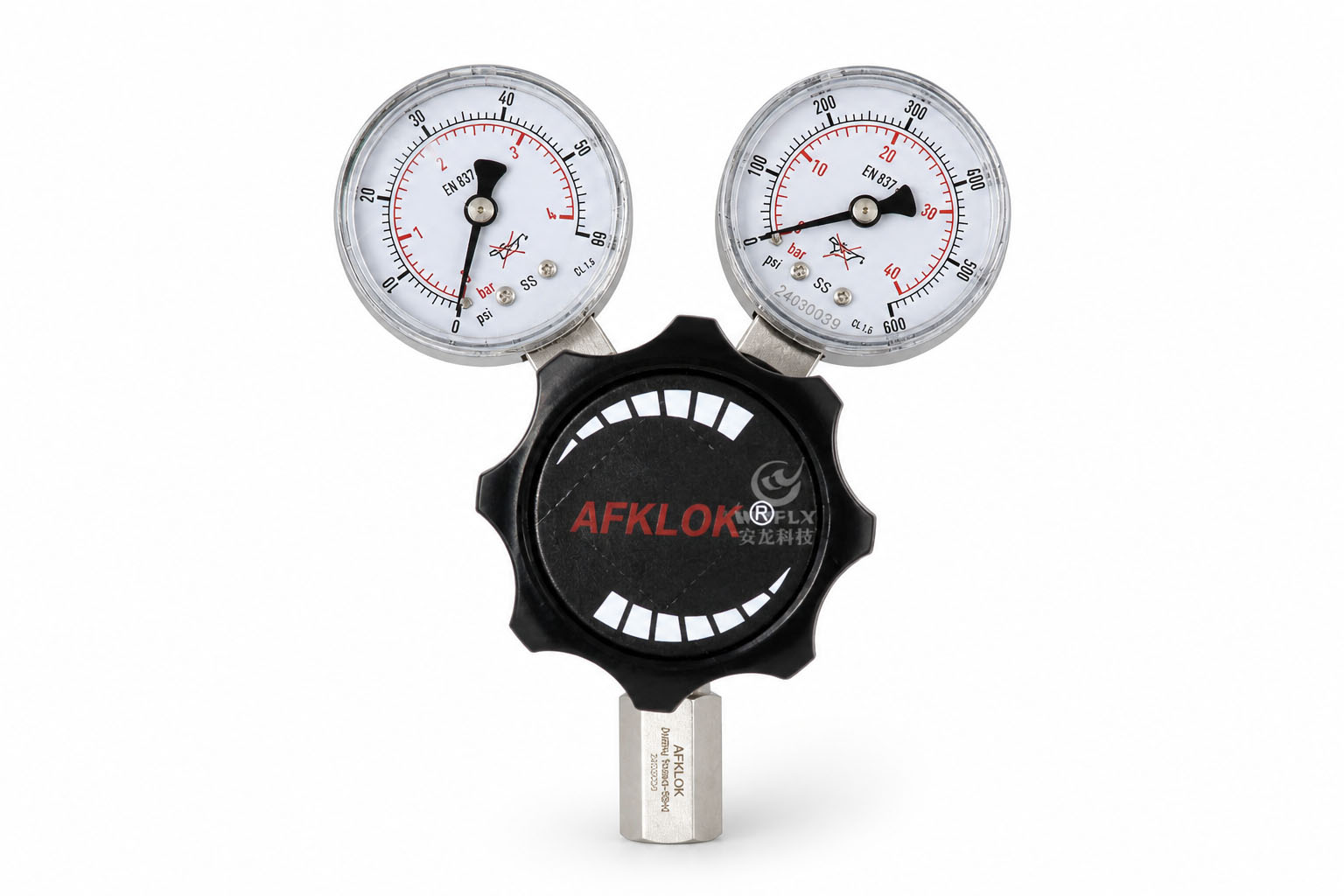
To prevent sizing errors, fluid engineers must evaluate actual performance curves rather than relying solely on wide-open $C_v$ values. The WR11 nitrogen flow curves characterize pressure droop as flow increases across varying inlet supply conditions.
3.1 High Inlet Pressure Performance (1000 to 3000 PSIG)
Under high cylinder supply pressures (3,000 PSIG / 206.8 bar, 2,000 PSIG / 137.9 bar, and 1,000 PSIG / 68.9 bar):
- 500 PSIG Outlet Setpoint: As flow increases from 0 to $20.4\ \text{Nm}^3/\text{h}$ (340 SLPM), the delivery pressure experiences only a minor droop of 15 to 20 PSIG. The curve remains remarkably flat up to $34.0\ \text{Nm}^3/\text{h}$ (566 SLPM) before tapering as maximum poppet stroke is reached.
- 100 to 300 PSIG Setpoints: Even when the gas cylinder decays from 3,000 PSIG down to 1,000 PSIG, the WR11 maintains outlet stability within 5% to 8% of setpoint across standard laboratory consumption flows ($0 \text{ to } 27.2\ \text{Nm}^3/\text{h}$ or 453 SLPM), proving the dynamic authority of its convoluted metallic sensing diaphragm.
3.2 Low Inlet Pressure Dynamics and Droop Mitigation (100 to 400 PSIG)
When deployed as a secondary point-of-use regulator fed by a facility header (inlet pressures of 100, 200, 300, and 400 PSIG):
- Differential Pressure Limits: With a 100 PSIG inlet and a 50 PSIG outlet setpoint, available differential pressure ($\Delta P$) is limited. As flow exceeds $20.4\ \text{Nm}^3/\text{h}$, the droop slope steepens due to acoustic velocity limits through the orifice.
- Optimized Header Inflow: With inlet pressures of 300 to 400 PSIG and delivery pressures of 100 to 200 PSIG, the flow curves demonstrate expansive linear working plateaus between 0 and $34.0\ \text{Nm}^3/\text{h}$, providing robust droop resistance.
3.3 Engineering Safety Margins for Continuous Flow Systems
When sizing fluid systems using the WR11:
- Target steady-state operational flows within 30% to 70% of the linear section of the flow curve (typically 15 to 30 $\text{Nm}^3/\text{h}$ or 250 to 500 SLPM under cylinder pressures).
- For low-pressure header applications, always verify minimum expected inlet supply pressure during peak plant demand to ensure the regulator remains above its flow choke threshold.
4. Complete WR11 Model Number Coding and Ordering Selection Matrix
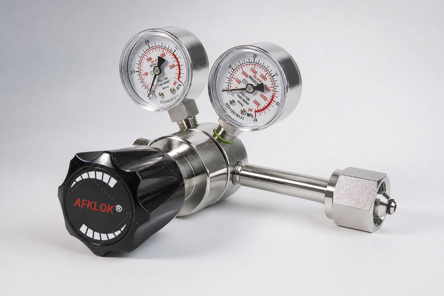
The WR11 Series utilizes a structured alphanumeric code that fully specifies all metallurgy, pressure ratings, port orientations, connections, and mounting accessories.
4.1 Deconstructing the Model Code Structure (Example: WR11-6L-35-100-D-00MM00-Z)
The ordering code is structured into seven discrete segments: WR11 - [Body Material] - [Inlet Pressure P1] - [Outlet Pressure Range P2] - [Port Configuration] - [Ports 1 2 3 4] - [Mounting]
Example Breakdown: WR11 - 6L - 35 - 100 - D - 00 M M 00 - Z
- WR11: Model Series (Single-Stage High-Purity Diaphragm Pressure Regulator);
- 6L: 316L Stainless Steel body;
- 35: Maximum inlet pressure of 3,500 PSIG;
- 100: Outlet pressure control range of 0–100 PSIG;
- D: Type D porting configuration (2-In / 2-Out);
- 00 M M 00: Clockwise port connections (Port 1: 1/4" NPT female inlet; Port 2: high-pressure gauge; Port 3: low-pressure gauge; Port 4: 1/4" NPT female outlet);
- Z: Includes one panel mounting nut.
4.2 Comprehensive Ordering Matrix for Body Materials, Pressures, and Ports
| Code Segment | Option Code | Specification Details | Typical Engineering Application |
|---|---|---|---|
| Body Material | 6L<br>HC | 316L Stainless Steel<br>Hastelloy C-276 | General high-purity, inert, and non-corrosive gases<br>Severe sour gas, wet chlorine, toxic acid vapor |
| Inlet Pressure ($P_1$) | 35<br>06 | 3,500 PSIG ($C_v = 0.09$)<br>600 PSIG ($C_v = 0.20$) | Gas cylinder manifolds, primary high-pressure drop<br>Secondary distribution headers, downstream skids |
| Outlet Range ($P_2$) | 30 / 60 / 100<br>150 / 250 / 500 | 0–30 / 0–60 / 0–100 PSIG<br>0–150 / 0–250 / 0–500 PSIG | Carrier gas delivery, purge blankets, low-pressure cells<br>Autoclaves, reactor pressurization, pilot test lines |
| Port Configuration | A / B / D | Type A (1-In/1-Out) / Type B (1-In/2-Out) / Type D (2-In/2-Out) | Inline piping / Single gauge monitoring / Dual gauge monitoring |
| Port Connections (1–4) | 00<br>01<br>10 / 11<br>20 / 21<br>M<br>C___ / DIN___ | 1/4" NPT Female<br>1/4" NPT Male<br>1/4" / 3/8" Fractional Tube Fitting<br>6mm / 8mm Metric Tube Fitting<br>Mounted Dual-Scale Pressure Gauge (PSI/MPa)<br>CGA Cylinder Nut & Nipple / DIN Cylinder Fitting | Standard threaded piping<br>Nipple adapters<br>Imperial high-purity instrumentation tubing<br>Metric instrument tubing lines<br>Inlet and outlet visual pressure readout<br>Direct gas cylinder valve connection |
| Mounting Style | [Blank]<br>Z | Standard Base Mounting (2×M5 bottom holes)<br>Panel Mount (Includes 1 Panel Mounting Nut) | Bracket or rigid tube support<br>Instrument console and control cabinet installation |
4.3 Gauge Options and International Cylinder Connector Compatibility (CGA / DIN)
For cylinder regulator configurations:
- Specifying a CGA number (such as CGA-580 for nitrogen/argon/helium, CGA-540 for oxygen, or CGA-350 for hydrogen) or a DIN number (such as DIN-1, DIN-6) automatically equips Port 1 with a factory-tested cylinder connection nut and nipple.
- The M gauge option provides dual-scale (PSI / MPa) stainless steel pressure gauges calibrated to the regulator's inlet and outlet ratings, eliminating the need for aftermarket pipe fitting assembly.
5. Industrial and Laboratory Application Scenarios
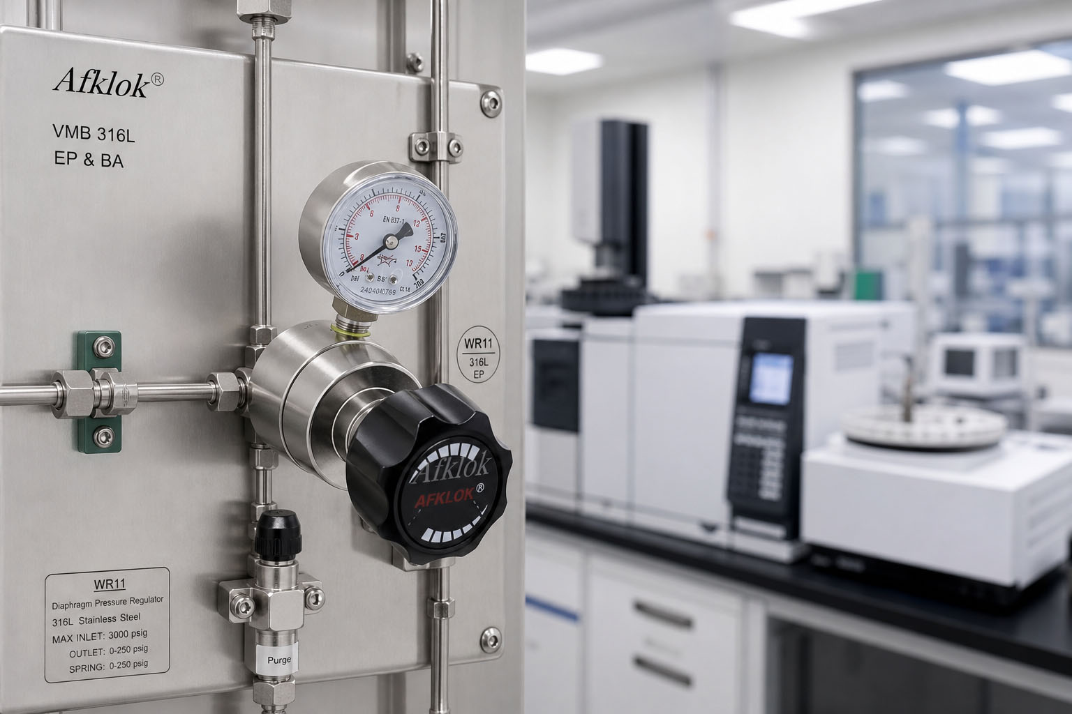
The high leak integrity and corrosion-resistant construction of the WR11 make it an industry benchmark across critical process sectors.
5.1 Analytical Instrumentation, Corrosive Gases, and Toxic Media
Analytical instruments like Gas Chromatographs (GC-FID, GC-TCD), Mass Spectrometers (GC-MS, ICP-MS), and Atomic Absorption Spectrometers require carrier and fuel gases (helium, argon, hydrogen, zero air) with setpoint drift under 0.1 PSIG.
- Purity Preservation: The non-lubricated PCTFE seat and metallic diaphragm prevent hydrocarbon leaching that causes spectral baseline noise.
- Corrosive Media Defense: When handling hydrogen chloride (HCl), hydrogen sulfide ($H_2S$), or sulfur dioxide ($SO_2$), the HC (Hastelloy C-276) option prevents pitting corrosion and stress cracking.
5.2 Semiconductor Cleanrooms and Oxygen-Enriched Clean Services
- Valve Manifold Boxes (VMB / VMP): In photolithography and wafer fabrication lines, the helium leak rate of $\le 1 \times 10^{-9}\ \text{mbar}\cdot\text{l/s}$ ensures zero atmospheric ingress and total containment of toxic dopants.
- Oxygen Cleanliness: High-pressure oxygen expansion poses severe ignition hazards if organic hydrocarbons are present. The factory ASTM G93 Level C cleaning protocol ensures complete degreasing, rendering the WR11 intrinsically safe for oxygen service.
6. Common Failure Prevention, Installation, and Maintenance Guidelines
Adhering to proper engineering practices during installation and commissioning ensures years of reliable regulator operation.
6.1 Inlet 20-Micron Filter Maintenance and Seat Creep Prevention
The most common field failure in pressure regulators is pressure creep—a gradual, uncontrolled rise in downstream pressure when downstream isolation valves are closed.
- Root Cause: In over 90% of cases, creep is caused by microscopic particulates (metal shavings, thread tape shreds) becoming trapped between the PCTFE seat and the stainless poppet, preventing a bubble-tight shutoff.
- Prevention: Always crack open cylinder valves briefly (snifting) to blow away dust before connecting the regulator. Inspect and clean the WR11's internal 20-micron sintered filter periodically if differential pressure across the inlet rises abnormally.
6.2 Helium Leak Checking, Pressurization Sequencing, and Cycle Purging
- Thread Sealant Discipline: Never use low-grade PTFE tape that shreds into the flow path. Apply anaerobic PTFE paste or cleanroom-grade PTFE tape, ensuring the first two threads remain bare to prevent debris ingestion.
- Pressurization Sequence: Before opening the gas supply, rotate the black control knob counterclockwise until it turns freely (unloading the main range spring). Slowly open the cylinder valve to establish inlet pressure, then rotate the knob clockwise to reach the target delivery pressure. Opening a supply valve against a fully loaded regulator can hydraulically shock and rupture the diaphragm.
- Purge Protocols: In toxic or pyrophoric installations, execute at least 10 high-purity nitrogen cycle purges (pressurize and vent) before introducing hazardous media, reducing internal moisture and oxygen to sub-ppm levels.
7. Frequently Asked Questions (FAQ) About WR11 Pressure Regulators
7.1 Why is the Cv rated at 0.09 for 3500 PSIG inlet but 0.20 for 600 PSIG inlet?
At 3,500 PSIG inlet pressures, fluid velocity through the throttling orifice easily reaches sonic (choked) conditions. A smaller orifice diameter ($C_v = 0.09$) restricts fluid shear stresses, minimizes seat erosion, and provides micro-fine setpoint resolution. At 600 PSIG, the lower pressure differential requires a larger orifice area ($C_v = 0.20$) to deliver high volumetric throughput without excessive restriction.
7.2 What does ASTM G93 Level C cleaning signify for toxic and oxygen gas lines?
ASTM G93 Level C mandates that non-volatile organic surface residues (oils, greases, solvents) must remain strictly below $66\ \text{mg/m}^2$, verified by quantitative solvent extraction. For oxygen service, this eliminates catastrophic combustion risks caused by adiabatic compression heat. For analytical gases, it eliminates hydrocarbon contamination that disrupts sensitive detectors.
7.3 How are the ports arranged in the Type D (2-in / 2-out) configuration?
The Type D configuration uses four orthogonal ports: Port 1 is connected to the high-pressure gas supply; Port 2 receives the high-pressure inlet gauge to monitor remaining cylinder pressure; Port 3 receives the low-pressure outlet gauge to monitor delivery setpoint; Port 4 connects to the downstream process line.
7.4 How can I order a regulator with factory-installed CGA or DIN cylinder connections?
In the ordering matrix, substitute the Port 1 code with your designated CGA or DIN standard (e.g., C580 for inert gases, C540 for oxygen, or C350 for hydrogen). The regulator will be factory-assembled and leak-tested with the appropriate nut and nipple connection, enabling direct cylinder hookup.
8. Engineering Summary and Procurement Best Practices
The WR11 Series Diaphragm Pressure Regulator combines 3,500 PSIG inlet containment, broad outlet adjustment ranges, helium leak integrity ($\le 1 \times 10^{-9}\ \text{mbar}\cdot\text{l/s}$), and certified ASTM G93 Level C cleanliness. Whether deployed on analytical gas chromatography lines, semiconductor wafer tools, or toxic chemical sampling headers, the WR11 provides droop-resistant performance and long service life.
Before issuing purchase orders or releasing piping and instrumentation diagrams (P&IDs), verify your engineering specifications against this practical checklist:
- Operating Pressure Boundaries: Match your maximum supply source against the 600 PSIG ($C_v=0.20$) or 3,500 PSIG ($C_v=0.09$) inlet configurations, and select an outlet spring range that places your target setpoint near the center 50% of the scale.
- Chemical and Media Compatibility: Specify 316L stainless steel for general inert and ultra-high-purity gases, or upgrade to Hastelloy C-276 for wet chlorine, hydrogen chloride, or aggressive acidic streams.
- Mounting and Enclosure Requirements: Determine whether the installation requires base M5 threaded mounting or panel mounting (code suffix Z) for front-console instrument integration.
- Porting and Gauge Layout: Confirm whether single-gauge (Type B) or dual-gauge (Type D) monitoring is necessary, and specify standard 1/4" NPT threads, double-ferrule compression tube fittings, or pre-assembled CGA/DIN cylinder fittings.
- Inlet Filtration Safeguards: Confirm that process media entering the regulator is free from scale and weld spatter; the built-in 20-micron 316L sintered filter serves as the primary barrier against seat creep and premature maintenance.
Consult with factory-trained fluid power engineers to review your volumetric flow curves and piping schematic, ensuring your gas control infrastructure achieves optimal accuracy, regulatory safety, and long-term operating uptime.